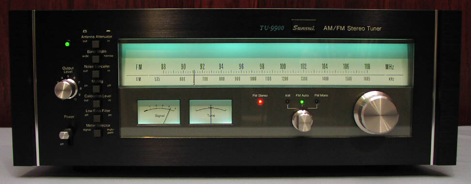
The Sansui TU-9900 is a favorite among audio enthusiasts and modifiers. Allow it's been 40 years since its introduction, this tuner still holds its own today.
This page documents some of the modifications that I've made to mine. Hopefully, this page will serve as a source of ideas and/or inspiration for others. I do not go into a lot of detail here. Capacitors, resistors, and transistors were replaced or eliminated in places. Many of the resistors were replaced with 1% metal film types. The factory 7 pin op-amps were replaced with a small circuit board that sits on pins above the multiplex board. It is not pictured here, but is pretty straightforward and uses an OPA2604 bypassed with 0.1 uF caps on the daughter card. If you have questions that you can't answer for yourself or by examining the material here, feel free to email me with questions.
All of the electrolytic capacitors were removed. I replaced most of them with Nichicon Muse or other high quality types. Others were bypassed because the low DC offset of the replacement op-amps negated their necessity or were replaced with film types. I replaced the diodes in the discrete portion of the multiplex decoder with 1N5711s.
I used aqua or cyan colored LEDs as replacements for the incandescent lamps originally used to illuminate the dial and meters. I mounted Luxeon Stars to the sheet metal that enclosed the dial lamps, using the metal as an effective heat sink. The LEDs are fed filtered DC to prevent line frequency flicker.
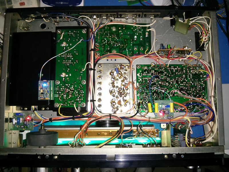
This is a shot of the bottom of the tuner. Most of the modifications had been completed at this point. The glow of the front panel reasonably portrays the color of the LEDs that I used. The rectifiers and filter for the LEDs is partially visible near the front. The post-detection filter board is visible on the left, near the flywheel. The narrow IF filter board is a couple of inches to the upper right of the post-detection filter, plugged into the FM IF board. The audio injection amplifier board is visible, mounted near the front of the tuner over the edge of the multiplex board. I provide details of each of these three boards in the following section.
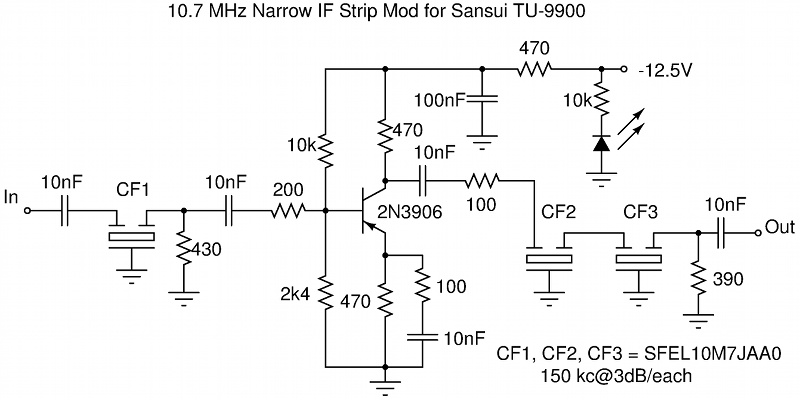
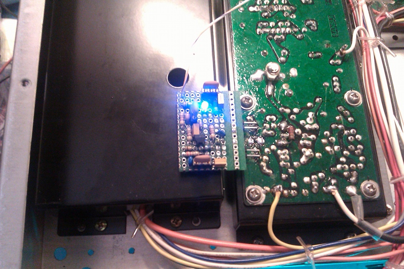
The stock narrow mode IF filter of the TU-9900 was a SAW filter. Mine had pretty much died of old age - with a non-symmetrical response that was no longer well centered at 10.7 MHz. By modeling the nearby circuitry of the tuner, I was able to get a fairly simple circuit that presented each of three 150 kHz ceramic filters with close to 300 ohm source and termination impedances while providing a modest amount of gain to offset the increased amount of loss the filters possess. By sweeping the IF filter, using a Sound Technology ST-1000A, I was able to select a group of three ceramic filters that were well centered and provided a symmetrical response. The tuner has no problem receiving KUAT at 90.5 MHz from a distance of 100 miles despite the existence of a local first-adjacent station at 90.3 MHz while using a two foot long piece of hook-up wire. Switching the tuner to narrow mode is enough the significantly reduce IBOC self-noise... although not completely. The single wire running from the board supplies the -12V to run the transistor.
The best sounding FM stations, generally speaking, are those with the greatest dynamic range. Higher dynamic range correlates with increased perception of IBOC self-noise. The two worst offenders at my location are a classical station: KBAQ at 89.5 MHz, and a jazz station: KJZZ at 91.5 MHz. IBOC self-noise manifests itself as a hiss present when listening to stereo. It is caused by the multiplex decoder when it mixes odd-order harmonics of the 38 kHz L-R sub-carrier with the IBOC digital sidebands between 100 kHz and 200 kHz. While not all FM tuners suffer from this phenomena, that vast majority of them do. The inspiration for this circuit comes from Brian Beezley. His web page covering this topic is: here.
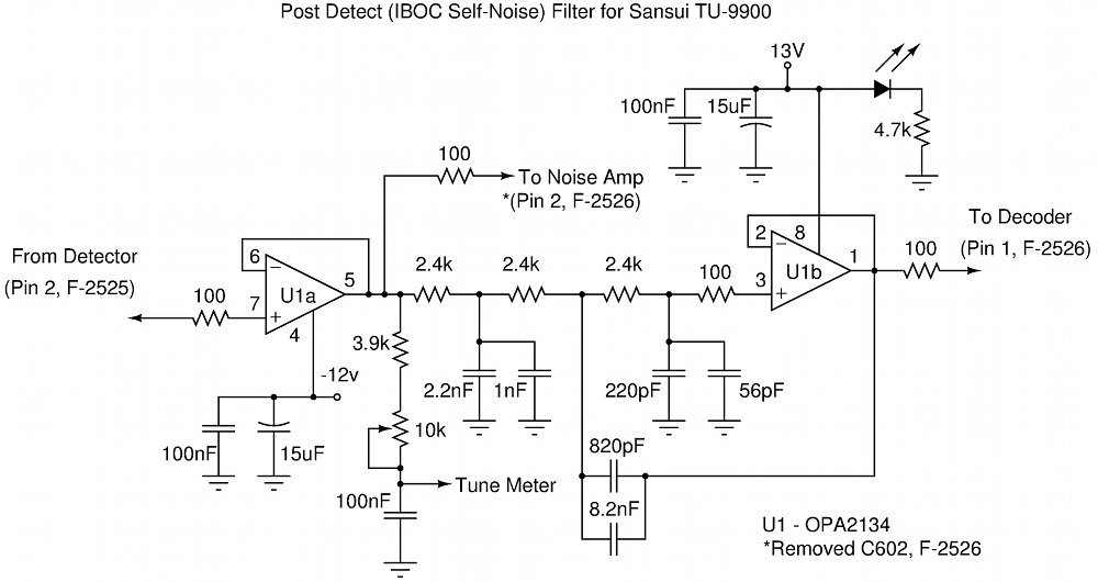
Below is the schematic of my implementation of the filter, along with a photo of the completed board. I took advantage of having a buffered detector output to create an adjustable drive for the center-tuning meter. I always felt that the performance of the stock meter and circuit was somewhat weak. While low-pass-filtered composite audio is fed to the mixer stage of the multiplex decoder, unfiltered composite signal is fed to the PLL input, as well as the noise amp. This allows for normal operation of the muting circuit.
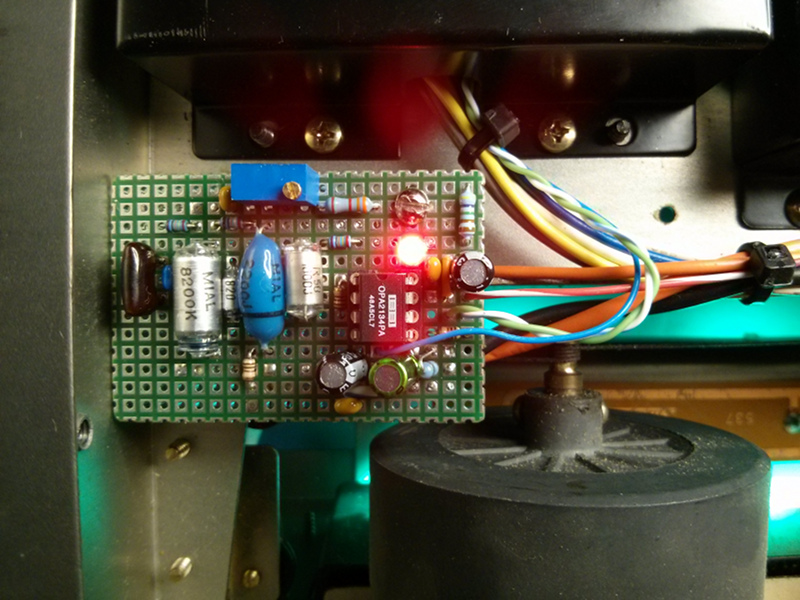
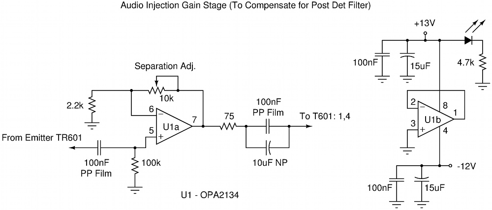
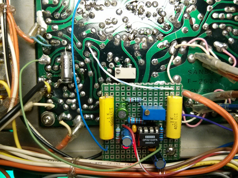
The post detection filter I used has significant roll-off in the frequency range that the L-R sidebands reside and presents some phase shift between 19 kHz and 38 kHz. In order to restore proper function of the multiplex decoder, I needed to increase the audio signal level presented to the mixer of the multiplex decoder circuit and phase shift the 19 kHz signal presented to the HA1156W chip's PLL circuit. The schematic and photo below show the amplifier circuit and board. Visible in the photo is a hand-selected 1000 pF cap I placed in parallel with C609, a 680 pF emitter bypass cap that provides some phase lead to the signal fed into the PLL chip. Both of the stereo separation adjustments that were originally accessed on the top of the multiplex board are now accessed from the bottom. The injection level is set by the trimmer on the injection amp board, while the balance adjustment is set by a trimmer soldered to the bottom of the multiplex board near the new amp board. Both are visible in the photo.
Note: I ended up feeding the PLL circuit unfiltered composite audio. The amount of phase delay imposed by the filter at 38 kHz is large enough that the unfiltered 19 kHz would have to have more than 90 degrees of phase lag added to bring the phase of the pilot tone, and therefore the timing of the derived 38 kHz oscillator of the multiplex decoder, into proper alignment for decoding of the L-R signal and the full realization of stereo separation. I instead chose to impose some phase lead to the 19 kHz pilot tone fed to the PLL chip. This causes the 38 kHz signal to be exactly 180 degrees out of phase from where it should be: L-R becomes R-L, and vise-versa. I swapped the wires at the output of LP1 ( L <-> R ) in order to resolve this issue and get the stereo channels coming out of their correct output jacks. As is often the case, there is more then one way to come up with the same result.
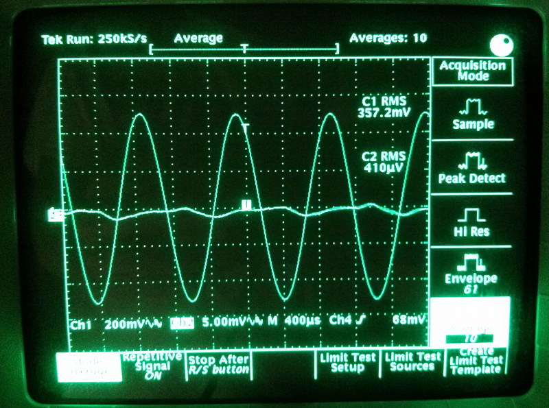
Below is presented evidence of the results of my efforts to correct the operation of the tuner's multiplex decoder after installation of the IBOC self-noise filter. Better than 58 dB separation was measured. The stock specification for the tuner is 50 dB. With all of these changes in place, I am now able to enjoy FM broadcasts relatively free from IBOC self-noise with the IF bandwidth set to 'Wide', and in glorious stereo.