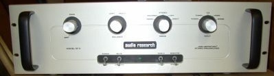
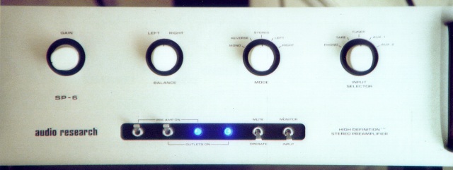
In July, 2002 I picked up a 1978 Audio Research SP6 preamp. Here is a photo from the original Ebay ad where I found and bid on it.
The unit was in very good condition but badly in need of repair. This preamp had an above average power supply with 11 large twist-lok can capacitors. All of these capacitors needed replacement. Because of the high cost and very limited availability of this now obsolete style of capacitor, I decided to modernize a bit and upgraded to modern Panasonic(tm) electrolytics. This meant that somewhere along the line I would have to re-layout the caps and drill some holes in the printed circuit board.
Upon studying the schematic for the unit, I found that I didn't care for the line stage circuit as it left the factory. This circuit had more gain than I needed, a relatively large amount of negative feedback, and a higher 'real world' output impedance then what I wanted to live with. The phono stage is a fairly conventional design with two grounded cathode gain stages followed by a cathode follower. The equalization circuit is in the negative feedback loop. Although it was nothing fancy or elaborate, it appeared to be well designed and has been reviewed as being one of the best sounding ARC phono stages of all time. I chose to leave the design of the phono stage alone and just rebuild it using higher quality parts.
I had a few ideas for an improved line stage but I would need to come up with an increased amount of current for the line stage's cathode follower and a new regulated supply voltage for the gain stage. This meant that the power supply would have to be re-engineered a bit to supply the new line stage....
Realizing how far I was going to get into this project, I decided to do a complete restoration and modification and completely stripped the circuit board and chassis. I ordered Cardas(tm) RCAs, Musicaps, Holco resistors, Vishay resistors, Caddock resistors, Kimber wire and isolation feet from Welborne Labs, as well as new toggle, mode and input switches directly from Audio Research in Minnesota. The volume pot was replaced with a Black Beauty Alps that I had on hand. A stepped attenuator was purchased and assembled for the project but wouldn't physically fit when the unit was being reassembled. Metal film and carbon composition resistors, LEDs, electrolytic capacitors, JFETs, HEXFREDs and trimpots were purchased from Digi-Key.
Here is a schematic of the new line stage. Since all of the music must pass throught the line stage, little expense or time was spared here. It would have been impossible to fit a 20uF Musicap into the preamp for the output. I used a pair of 10uF Solen(tm) caps bypassed with a healthy sized Musicap. The 4.75K and 562K resistors in the line stage are Holcos and all the rest are Caddocks. The resistors used in the phono stage are Holcos and Vishays.
Note the liberal use of parasitic suppressors. I wanted this stage to sound very fast and detailed, but be completely free of the harshness that often plagues wide bandwidth designs. The currrent level through the follower stage is 5mA. I felt 5mA would be about the minimum acceptable here in order to be able to easily drive modern high end interconnects, as well as the passive line level crossover that I used. The circuit is a common cathode gain stage using a pair of 12AX7 triodes, with the output direct coupled to a cathode follower consisting of a triode from a 12AZ7. Thanks go out to the Tube Cad Journal for the idea to use this circuit topology.
In order to get near ideal operation, a JFET was used as a constant current sink as the load for the common cathodes. I went one step further and made the current level adjustable thereby allowing for a balance adjustment. This allows compensating for variations in 12AX7s and helps to keep the operating points of the two sides of the gain stage the same.

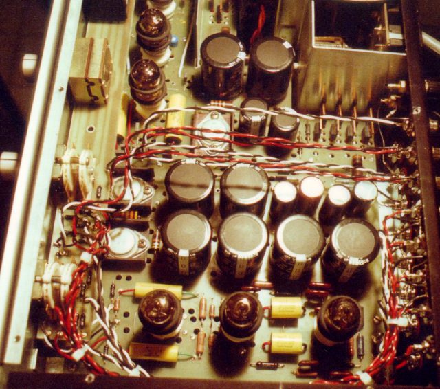
ARC did some neat things with the design of this preamp. The power supply consisted of three active regulated rails, each bypassed at the output with 400uF of capacitance. I added an additional rail (200V) and made a moderate increase in the size of all of the filters. I also used HEXFREDS for the rectifiers in the high voltage and each of the two filament supplies. All filaments are run on DC in this preamp. One of the filament supplies is active regulated at 24V. By grounding the positive side of this supply, I was able to come up with the -24V rail to feed the JFET current sink. The grounding technique in this design seems to follow a methodology that I have tried to practice in the past. The ground follows the signal path. It starts at the input filters and runs along the regulators. It then leads from the output side of the line stage to the input side of the line stage, then the output side of the phono stage and finally ends at the lowest noise point in the preamp-the input to the phone stage. If executed properly, ground induced noise levels are lower than they would be with a star-ground technique.
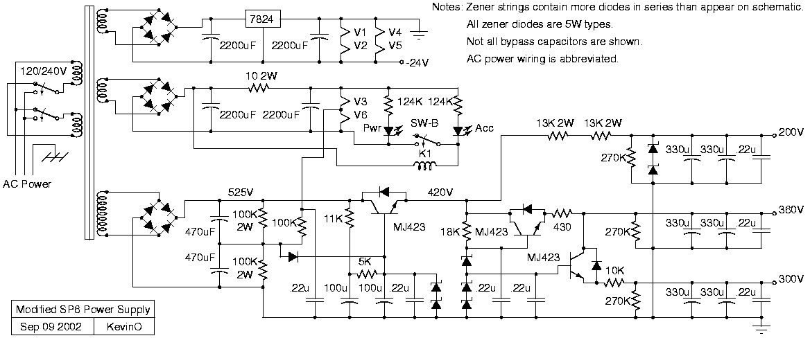
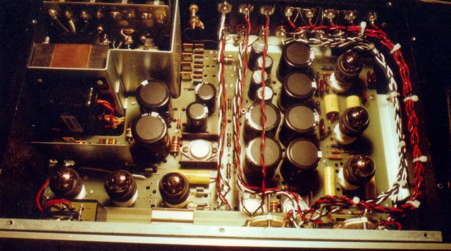
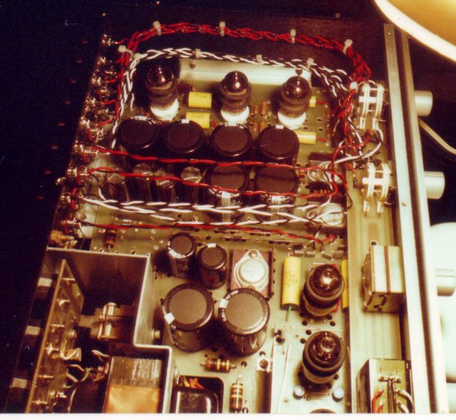
In the original ARC design, each of the electrolytics was bypassed by a .2uF film capacitor. A .1uF Auricap or Musicap was used as an additional bypass for each rail of each channel as physically close to the load as possible. The -24V rail was bypassed near the JFETs also. Although the constant current stage represents an almost infinite AC impedance, it doesn't hurt to try to make the rail as quiet as possible. The bypass caps are visible in the following photos. The slide switch at the back of the unit was for adjusting the amount of feedback, and hence the gain, of the line stage. The current design no longer uses it.
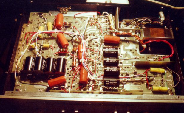
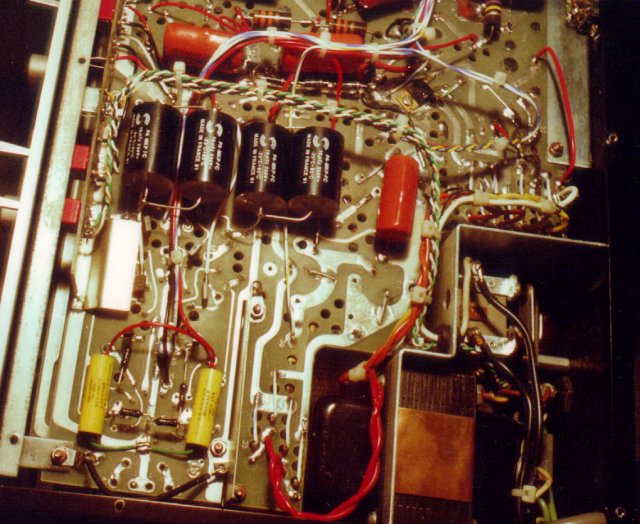
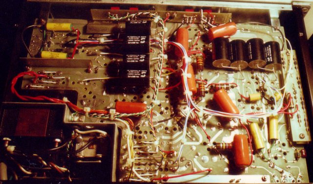
Also evident in the photos are the large black Solen caps, wired in pairs and used as the output couplers for the phono and line stages. These were bypassed with Musicaps which are located on the top of the circuit boards. The relatively large output caps were to used to both extend the low frequency response and minimize the phase shift. Note that the output cap is the only capacitor in the signal path for the line stage, and one of only two in the signal path of the phono stage. The large carbon comp resistors that you see in the photos are used as bleeder resistors for the large electrolytics or as current sources for zener strings. They are extremely reliable resistors in this service and low noise or tight tolerances are of little value here.
The next photo shows the back of the unit. I used Cardas RCA jacks and you may notice that the red washers are on the upper ones. This is the only piece of gear I have that has the right channel on top and the left on the bottom, but that is the way ARC made it and I kept it that way.
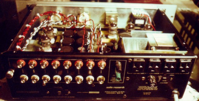
The binding posts on the back of the unit allow you to run the unit with the signal ground either tied to the chassis (earth ground) or left floating. The unit came from the factory with a 12 gauge three conductor power cord. The phono input has its own grounding post and it is mounted near the phono inputs.
The following photo shows a shot from the front looking down at a slight angle. The preamp originally had green LEDs to indicate main and auxillary power. I like the blue ones better. I used ultra bright LEDs and started off with one half of the original 20mA of current for each one. They were blindingly bright and would light up a good portion of the living room at night. I am currently running the LEDs with a current level of 180uA each and they seem about right. I wanted the best electrical connections possible throughout the preamp so I replaced all of the switches and controls. All of the switches (Mode, Input and toggle) were factory replacements that were ordered and promptly shipped from Audio Research.
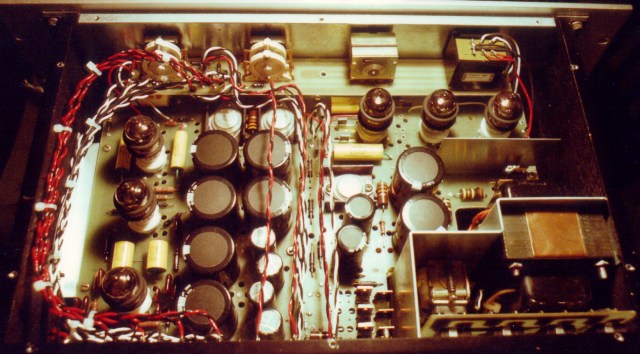
The following photos show views of the top side of the preamp. The three tubes in the front are for the line stage and the three on the side are for the phono stage. The two trimpots to adjust the bias of the line stage are visible near the base of the middle tube of the line stage. The JFETs that they control are on the bottom. Also visible are the tube damper rings, two per tube. The tube sockets are ceramic with silver plated contacts.
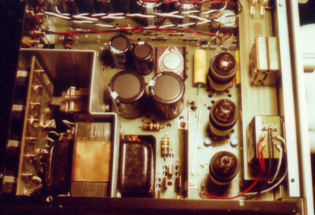
The TO-220 case devices at the back and the side of the unit are the HEXFREDs. The eight at the back are for the filament supplies and the four near the left of the unit are for the high voltage. They are all rated at 1200V PIV and 6 amps of continuos current. Twisted pairs of Kimber wire were used for all of the signal connections to and from the circuit boards. The pairs near the right hand side of the unit are inputs and the pairs in the middle are the output and tape monitor loop connections. I left all of the functionality of the original controls, at the risk of a slight degradation in sound quality. I have an open reel tape machine and I wanted the flexibility of the tape loop. The careful choice of wire and connectors, the use of high quality audio grade toggles, and the termination of the signal wires using series resistors (Holco), kept this degradation to a minimum.
All of the inputs to the preamp are terminated also (the factory did this) and the resistors are visible in the photos, mounted near the input selector switch. An additional feature of doing this is the avoidance of shorting the output of a piece of gear when it is not selected by the switch. I have chosen values for these resistors that are higher than the ones in the original SP6 but a little lower than the ones used in the SP6a version.
How does the unit sound? To my ears, this is the best sounding preamp I have ever had in my system. It puts my Audible Illusion Dual-Mono to shame and it does it with 6 tubes instead of 8. Obvious differences between the units is the much larger and more sophisticated power supply of the ARC SP6, and the more sophisticated topology used in the Audible Illusion's phono stage. The overall sound is fairly neutral with only a slight sense of warmth. The unit doesn't seem to change its sonic character at all in response to even quite large changes in signal amplitude. Stereo imaging seems to be extremely good - better than the rest of my system could reveal.
The bass is tight and very controlled, very much like a high-end solid state unit, probably do to the higher output current and larger coupling caps. The midrange is well defined but not overly forward or sweet as is the case with many tube designs. A great deal of definition and dynamic accuracy is apparent in the mid to upper registers. The sound can be dark or bright but only in response to the material being played. Softer portions of the music, such as ambient cues, are easily discernable even with loud instruments playing in the foreground. The high frequency range is free of harshness and over-emphasis, yet extended. There doesn't seem to be any signs of 'politeness' or roll-off. The highs are smooth and well integrated with the rest of the range.
The preamp did respond well to an extended break-in period of a couple hundred hours with a very high level signal. It took some time for the unit to open up and display a wide soundstage and begin revealing some of the softer dynamics present in live jazz recordings. A DVD player and various disks of jazz and rock mp3s was used to allow break in to continue unattended. On the bench, the line stage had no problem producing in excess of 50 volts of output while generating a clean sine wave when terminated with a high impedance load.
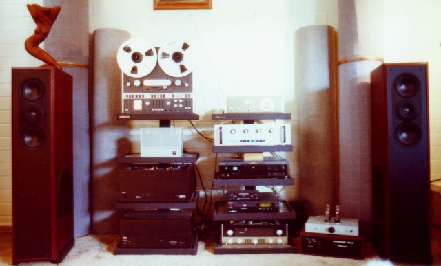
It would be somewhat inappropriate not to describe the other components that were in the system during listening tests. The speakers were Acoustic Research 312HO's with all of the original wiring and crossovers removed. The cabinets were stiffened by adding additional bracing. The preamp drove a passive two-way crossover with a 200Hz turnover frequency. The low pass side of the crossover was 3rd order and the high pass side was 1st order. The crossover fed a pair of Adcom power amplifiers. A GFA-555 MkII was directly connected to the woofers. A GFA-5800 was directly wired into the midrange drivers--two per side--and a 2nd order highpass crossover was used to drive the tweeter. The tweeter crossover consisted of a Hovland capacitor, an Alpha Core 14 gauge ribbon inductor, and a non-inductive Mills resistor. This combination produced 600 watts RMS per channel feeding speakers that are 97dB at 1 watt/1 meter. The speaker wires were Tara Labs Reference Gen 2 for the higher frequency drivers and some 8 gauge twin conductor wire from Van Den Hul for the woofers.
A Sony XA20ES CD transport/player, Apex DVD player, H.H. Scott 350B vacuum tube FM tuner and a Revox A700 tape deck were used for the front end. All of the interconnects were Tara Labs Reference cables. The equipment sat on Standesign equipment stands. A VPI brick sat on top of the CD player and some ASC Tube Traps were placed behind the speakers.
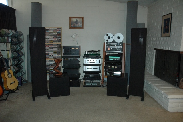
Much of the Hi-Fi system changed during the following five years. The high efficiency loudspeakers were replaced with low efficiency planar magnetic speakers--modified Eminent Technology LFT-8's--trading sound pressure level for improved midrange and high frequency definition. NHT SW3 subwoofers are used in place of the LFT-8 woofers to produce higher bass levels at lower distortion. The evolution of crossover designs to drive the power amplifiers abated with the acquisition of a Behringer DCX 2496 DSP based unit. Balanced lines are used to feed the power amplifiers. The GFA-555 MkII has been replaced with a Parasound HCA-2200. A new turntable purchase led to the desire for a better phono preamp better than the stock design in the SP6. Time constraints, as well as the limited available space in the SP6 for a more sophisticated design, led to the purchase of an Audio Research PH-5 hybrid phono preamp.
Despite the drastic changes made to the system over the years, the modified SP6 line stage circuit continues to occupy its position in the system; faithfully reproducing analog signals from vinyl and open-reel, as well as digital sources converted by a Monarchy Audio M22C DAC. The M22C is used to convert S/PDIF digital signals from the Sony XA20ES-- which still serves as a CD transport--and to convert S/PDIF from a Squeezebox player pulling music stored on a server in another room. We have yet to see any reason to pursue a better line stage.